UNDERSTANDING THE RELATIONSHIP BETWEEN CURRENT, TEMPERATURE, AND CONNECTOR RELIABILITY
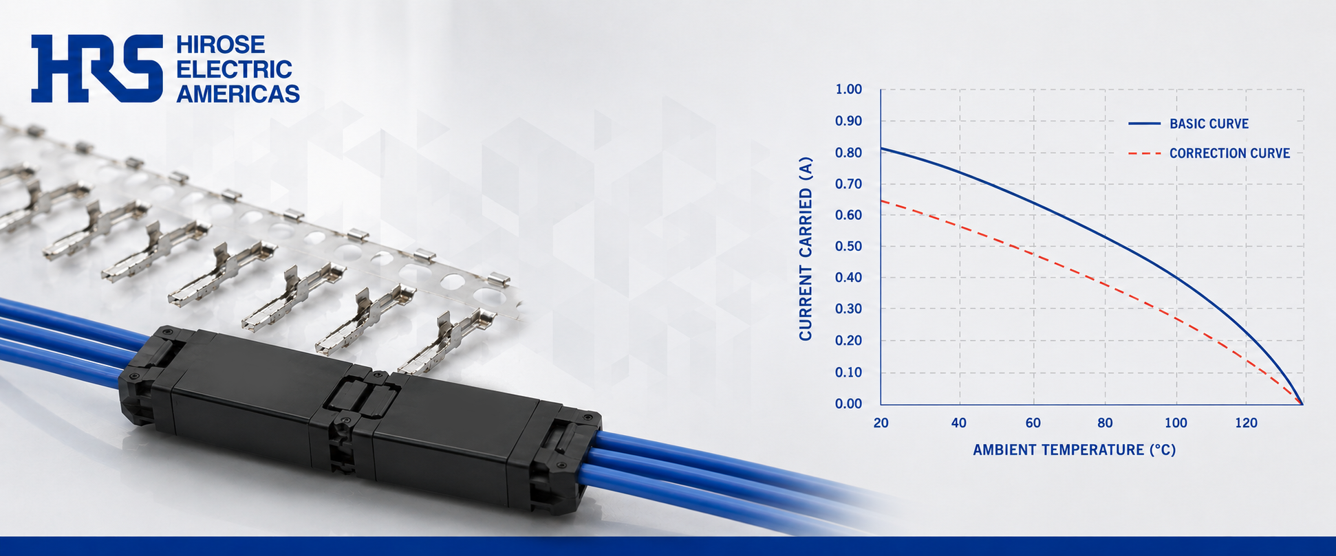
When designing electronic devices, ensuring reliability and safety under varying operating conditions is critical. One essential tool engineers use is the current derating curve, a graph that defines how much current a component can safely carry as ambient temperatures increase. Derating curves help prevent premature failures and preserve long-term performance.
This article provides an overview of connector derating curves and how to apply them during the design process.
Defining Derating Curves
A derating curve illustrates how the maximum allowable current for a connector decreases as ambient temperature increases. This relationship results from thermal effects generated as current flows through a contact interface. The derating curve for a mated connector pair is an essential design input when developing reliable electronic systems.
 Why Derating Curves Matter in Design
Integrating derating curves into the connector selection process enables engineers to define current limits based on real-world thermal environments, rather than just room-temperature lab conditions. This ensures connectors operate within safe thermal boundaries throughout the product’s lifecycle, helping to prevent failures due to overheating, excessive temperature rise, or material degradation.
Using precise derating data is critical for long-term product reliability and for meeting industry safety standards during both design and qualification phases.
Derating Curve Math
As current flows through a connector’s contact interface, it causes voltage drop and generates heat. The relationship between current, resistance, and heat generation is described by Ohm's Law and Joule's Law
| Equation | Purpose |
|---|---|
| V = I × R | Ohm's Law: Defines the relationship between voltage, current, and resistance. |
| P = I × V | Calculates power dissipated at the contact interface. |
| P = I²R | Joule's Law: Shows that heat generation increases with the square of current. |
Example: How Current Impacts Heat Generation
| Contact Resistance | Current | Voltage Drop | Power Dissipation |
|---|---|---|---|
| 20 mΩ | 0.3 A | 6 mV | 1.8 mW |
| 50 mΩ | 0.3 A | 15 mV | 4.5 mW |
| 50 mΩ | 3.0 A | 150 mV | 450 mW |
Key Takeaway: Because power increases with the square of current (I²), even modest increases in current can produce significantly more heat. In multi-contact connectors, this collective heating can elevate internal temperatures, increase resistance, and trigger a feedback cycle of additional power loss. This phenomenon is known as self-heating.
Key Factors that Impact Derating Curves
Connector derating behavior is shaped by three core factors:
- Self-heating
- Relative Thermal Index (RTI)
- Metal Relaxation
Self-heating

Self-heating in connectors occurs when contacts carry current, leading to localized temperature rise within the connector body. As current flows through each contact, electrical resistance generates heat (I²R losses). When these effects combine, they elevate the connector’s internal temperature, which can further increase resistance and accelerate degradation mechanisms.
This cumulative heating requires engineers to limit temperature rise within the connector to preserve safety and long-term performance. Left unchecked, self-heating can degrade contacts, accelerate oxidation, and cause failure due to metal fatigue or fretting corrosion.

Relative Thermal Index (RTI)
Relative Thermal Index (RTI) defines the long-term thermal endurance of insulating materials, such as the polymer housings used in connectors. RTI represents the maximum continuous-use temperature at which a material retains its critical electrical or mechanical properties over time, as evaluated under UL 746B.
In connector applications, RTI applies primarily to the insulating housing material. The insulating polymer typically defines the maximum allowable operating temperature before degradation occurs. When required, RTI documentation (UL Yellow Card data) can be provided to support material verification during compliance review.
If a connector operates above its RTI, insulation performance and mechanical integrity may deteriorate, potentially leading to system failure.
RTI is determined through long-term thermal aging tests that compare electrical and mechanical properties measured at room temperature with those measured after prolonged exposure to elevated temperatures.
Typical RTI classifications include:
- Mechanical Impact RTI
- Impact strength
- Mechanical Strength RTI
- Mechanical strength minus Impact
- Electrical RTI
- Insulating performance
In most connector designs, insulating materials typically reach their thermal limits before metallic contacts. Housing thickness, material selection, and molding design all influence long-term thermal stability.
Metal Relaxation
Metal relaxation, more specifically stress relaxation in connectors, is the time-dependent reduction in contact force when a metal is held under constant strain, such as in a deflected contact beam or spring within a connector.
During operation, particularly at elevated temperatures, contact displacement slowly becomes permanent due to relaxation. As this occurs, the normal force at the mating surface decreases.
Contact force is essential to maintaining a stable electrical interface. Reduced contact force increases contact resistance, lowers mechanical stability, and raises the likelihood of intermittent or high-resistance connections. Additionally, surface wear mechanisms such as fretting corrosion — caused by micro-movement or vibration between mating contacts — can gradually damage plating layers and increase contact resistance over time.
These increases in contact resistance can further elevate temperature rise due to resistive heating, accelerating stress relaxation and creating a compounding reliability risk. 
Some factors influencing stress relaxation include alloy composition, operating temperature, contact geometry, and plating durability.
Temperature Rise Rule (TRR)
The Temperature Rise Rule (TRR) ensures that a connector’s operating temperature — ambient temperature plus temperature rise caused by current flow — does not exceed its rated thermal limit.
When current flows through connector contacts, resistive losses (I²R) generate heat, raising the connector temperature above ambient.
Industry practice commonly references a 30°C temperature rise limit above ambient, as defined by Canadian Standards Association (CSA) standards and widely adopted across the connector industry. UL contributes additional connector safety requirements, including flammability classifications, terminal block temperature rise standards, and certification testing used to validate connector performance in regulated applications.
- CSA industry convention: 30°C temperature rise above ambient
- For VDE standards the temperature rise cannot exceed 45̊ C.
The combined value of ambient temperature plus temperature rise must remain within the connector’s rated temperature and RTI limits.
As described earlier, power dissipation follows Joule’s Law (P = I²R).
Because temperature rise is driven by power dissipation, connector temperature rise generally increases with the square of current: Trise ∝ I²
Creating a Derating Curve
Connector manufacturers do not control end-use environments. Therefore, electrical ratings must remain valid at the connector’s maximum rated temperature.

During qualification testing, current is incrementally increased while monitoring temperature rise until thermal equilibrium is reached. These data points are plotted to establish the tested performance curve.
Published current ratings are derived by applying a minimum 20% design margin to the tested curve. This conservative approach ensures reliable operation at maximum rated temperature and reduces the risk of thermal runaway under real-world conditions.
Conclusion
Connector derating curves are essential design tools for managing thermal risk and ensuring long-term reliability. By accounting for ambient temperature, self-heating, RTI limits, and stress relaxation effects, engineers can define safe operating current levels under real-world conditions.
Integrating derating analysis into connector selection improves system reliability, supports compliance with safety standards, and protects performance throughout the product lifecycle.
-----
connection point
Welcome to 'Connection Point' - your go-to spot for the latest in electronics. Here, we're all about connecting you with fresh ideas, engaging stories, and innovative solutions from Hirose Electric. Whether you're a tech enthusiast or an industry professional, there's something here for everyone.
Don't miss out on any of our updates – subscribe now and join our community of innovators and thinkers.
For more information on how Hirose Electric's connectors can transform your wearable device design, visit hirose.com or contact our team of experts today.